Initialising a Pipeline
Pipelines are important objects as they perform the work of transforming the collection of vertices stored in the vertex buffer into the pixel colour values of the final rendered image. This image is what is presented to the screen.
The Pipeline was briefly touched upon in Vulkan Concepts. The Pipeline object contains a configuration for the GPU’s graphics pipeline.
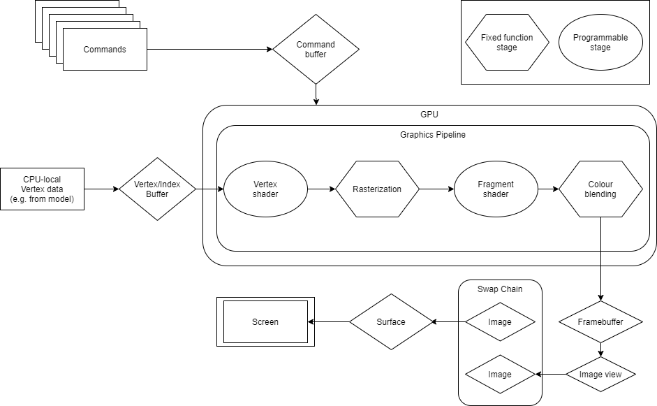
The several steps within the pipeline can be broadly categorized into two types:
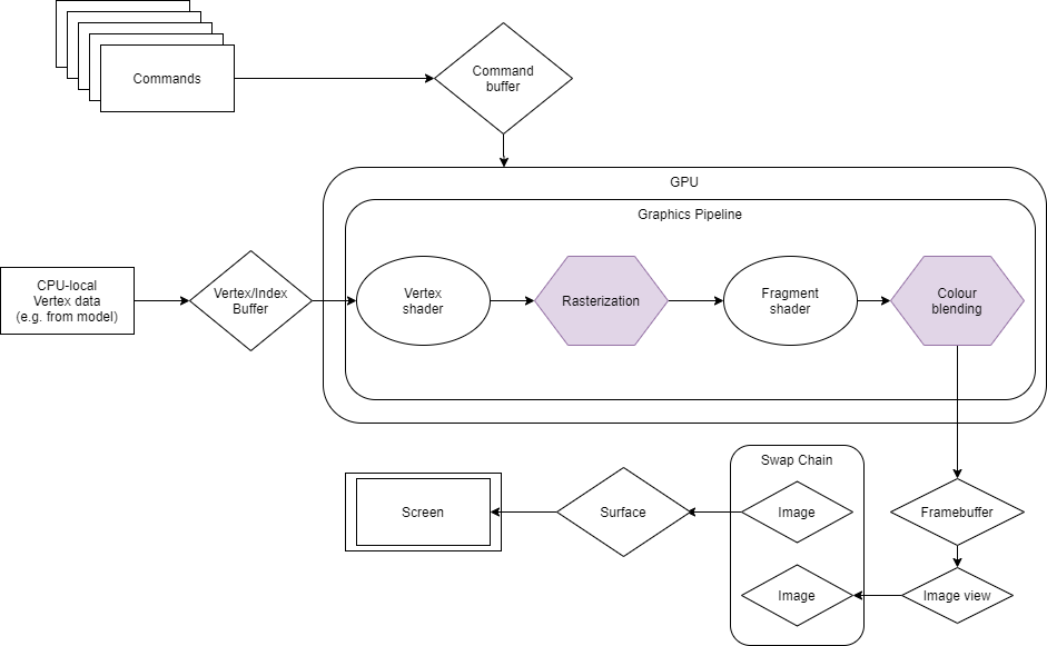
Fixed Function stages can be configured by the developer, but are not programmable as such. They perform standard operations which are generally required in many rendering scenarios, such as reading vertex data from the buffer at the start of the pipeline, culling back-facing polygons or converting primitives to discrete fragments (rasterization), or alpha-blending fragments. These are shown as hexagons in the diagram.
Programmable stages are under complete control of the developer through use of short programs called shaders. In this example, the application uses a vertex and a fragment shader. These have been set up in a previous section. These stages are shown as ovals in the diagram.
In Vulkan, the majority of the graphics pipeline configuration is stored in one immutable Pipeline object that is constructed in advance. This is because defining a pipeline is a costly operation, and so by doing it beforehand, Vulkan can drastically reduce the overhead during rendering. Additionally, in models where the pipeline is not explicitly created beforehand, the pipeline needs to check for validity just before use, which involves error-checking operations. These can have an unpredictable effect on performance varying between different hardware. This goes against one of the key principles of Vulkan, which is consistently deterministic performance across different GPUs.
Creating the Pipeline object involves populating the parameters of the fixed function stages of the pipeline and the shader modules to use from the ones defined earlier. Additionally, the descriptor set layouts and render passes are needed, but it is not necessary to create all the memory objects beforehand like in this tutorial, as they can be bound at render time.
The fixed function state information required when creating a pipeline is outlined below. As usual, the code in initPipeline() demonstrates what this looks like in an application.
Vertex input. This part of the pipeline receives vertices from the vertex buffer and requires the following:
VkVertexInputBindingDescription. The vertex binding description. This tells the GPU how to pass the vertex buffer data to the shader.
VkVertexInputAttributeDescription. The vertex input attribute description. This describes the format of the vertex attributes and how to retrieve them from the buffer. In this example, there are two attributes: the position co-ordinates and the texture coordinates.
VkPipelineVertexInputStateCreateInfo. This struct contains the configurations of the stage with references to the two other structs mentioned above.
Input assembler. This part of the pipeline contains the definition on how to construct primitives from the collection of vertices coming from the vertex buffer by defining the type of geometry, such as triangles, points, or lines, from the vertices. If an index buffer is being used, the input assembler can be set to restart primitive construction if a special value is given in the index buffer. These settings are chosen in the VkPipelineInputAssemblyStateCreateInfo struct.
Note
In the example code, the input assembler constructs triangles and an index buffer is not used. An index buffer is used in the majority of cases when multiple vertices form surfaces. This is because, in those cases, vertices used by multiple triangles would need to be replicated for each triangle they participated in.
- Rasterizer
This part of the pipeline converts the assembled polygons from a mathematical representation into actual fragments. Setting up this stage involves selecting:
Polygon mode. Whether the rasterizer should fill the polygon with fragments or just the edges.
Face culling mode. Whether to perform front face, back face, or no culling. This refers to not rendering primitives that are front or back facing.
Front face. Which winding order (clockwise or anti-clockwise) should be considered the front face of the polygon.
Line width. In the case of line primitives or wireframe polygon mode, the thickness of the rasterised lines.
Depth bias. The amount of any depth bias required, often used for shadow mapping.
Note
This is all set within the VkPipelineRasterizationStateCreateInfo struct. In the example code, polygon mode is set to “fill”, front face is “clockwise”, culling is enabled for back faces, and depth bias is not used.
- Colour blending
This stage describes how the pipeline should mix the colour values in the framebuffer when consecutive fragments are rendered on the same pixel of the screen by consecutive fragment shader invocations. Blending techniques can be used by setting the various blend factor and blend operation properties for colour and alpha channels. In the example code, colour blending is disabled so subsequent writes to the framebuffer at the same pixel will overwrite the existing colour values.
- Multi-sampling
This stage of the pipeline handles multi-sampling, which is generally used to implement anti-aliasing. This is not used in the example and so only samples once per pixel.
- Dynamic states
Vulkan allows some limited modification of the pipeline during runtime through dynamic states. This configuration can be modified with special Vulkan commands in the command buffer.
- Pipeline layout
A pipeline layout is used to describe what resources are required by the pipeline during rendering. These resources are accessed by the shaders through descriptor sets. Creating a pipeline layout involves specifying how many descriptor sets are needed and where to find them. The pipeline layout can also be used to specify push constants. These are a high-speed path to modifying constant data in shaders, but are not used in this example.
- Pipeline object
Finally, the actual pipeline object is created using vkCreateGraphicsPipelines().
void VulkanHelloAPI::initPipeline()
{
    // This is the description of the vertex buffers that will be bound, in this case it is just one.
    // The stride variable set here is the distance, in bytes, between consecutive vertices. The input rate
    // specifies at what rate vertex attributes are pulled from the vertex buffer. It can be set to: per instance or per vertex.
    VkVertexInputBindingDescription vertexInputBindingDescription = {};
    vertexInputBindingDescription.binding = 0;
    vertexInputBindingDescription.inputRate = VK_VERTEX_INPUT_RATE_VERTEX;
    vertexInputBindingDescription.stride = sizeof(Vertex);

    // This is the description of the vertex attributes for the vertex input.
    // The location variable sets which vertex attribute to use. In this case there are two attributes: one for
    // position co-ordinates and one for the texture co-ordinates.
    // The offset variable specifies at what memory location within each vertex the attribute is found, and the format
    // parameter describes how the data is stored in each attribute.
    VkVertexInputAttributeDescription vertexInputAttributeDescription[2];
    vertexInputAttributeDescription[0].binding = 0;
    vertexInputAttributeDescription[0].format = VK_FORMAT_R32G32B32A32_SFLOAT;
    vertexInputAttributeDescription[0].location = 0;
    vertexInputAttributeDescription[0].offset = 0;

    vertexInputAttributeDescription[1].binding = 0;
    vertexInputAttributeDescription[1].format = VK_FORMAT_R32G32_SFLOAT;
    vertexInputAttributeDescription[1].location = 1;
    vertexInputAttributeDescription[1].offset = 4 * sizeof(float);

    // Combine the vertex bindings and the vertex attributes into the vertex input. This sums up all of the information about the vertices.
    VkPipelineVertexInputStateCreateInfo vertexInputInfo = {};
    vertexInputInfo.sType = VK_STRUCTURE_TYPE_PIPELINE_VERTEX_INPUT_STATE_CREATE_INFO;
    vertexInputInfo.vertexBindingDescriptionCount = 1;
    vertexInputInfo.pVertexBindingDescriptions = &vertexInputBindingDescription;
    vertexInputInfo.vertexAttributeDescriptionCount = sizeof(vertexInputAttributeDescription) / sizeof(vertexInputAttributeDescription[0]);
    vertexInputInfo.pVertexAttributeDescriptions = vertexInputAttributeDescription;

    // Declare and populate the input assembly info struct.
    // This describes how the pipeline should handle the incoming vertex data. In
    // this case the pipeline will form triangles from the incoming vertices.
    // Additionally, an index buffer is not being used so primitive restart is not required.
    VkPipelineInputAssemblyStateCreateInfo inputAssemblyInfo = {};
    inputAssemblyInfo.sType = VK_STRUCTURE_TYPE_PIPELINE_INPUT_ASSEMBLY_STATE_CREATE_INFO;
    inputAssemblyInfo.flags = 0;
    inputAssemblyInfo.pNext = nullptr;
    inputAssemblyInfo.topology = VK_PRIMITIVE_TOPOLOGY_TRIANGLE_LIST;
    inputAssemblyInfo.primitiveRestartEnable = VK_FALSE;

    // Define the rasterizer.
    // Here the rasterizer is set to fill the polygons with fragments, cull back faces, define the front face
    // by the clockwise winding direction and not use any depth bias.
    VkPipelineRasterizationStateCreateInfo rasterizationInfo = {};
    rasterizationInfo.pNext = nullptr;
    rasterizationInfo.flags = 0;
    rasterizationInfo.sType = VK_STRUCTURE_TYPE_PIPELINE_RASTERIZATION_STATE_CREATE_INFO;
    rasterizationInfo.polygonMode = VK_POLYGON_MODE_FILL;
    rasterizationInfo.cullMode = VK_CULL_MODE_BACK_BIT;
    rasterizationInfo.frontFace = VK_FRONT_FACE_CLOCKWISE;
    rasterizationInfo.lineWidth = 1.0f;
    rasterizationInfo.depthBiasClamp = 0.0f;
    rasterizationInfo.depthBiasConstantFactor = 0.0f;
    rasterizationInfo.depthBiasEnable = VK_FALSE;
    rasterizationInfo.depthBiasSlopeFactor = 0.0f;

    // This colour blend attachment state will be used by the color blend info.
    // Only a single colour blend attachment is required because the render pass only has
    // one attachment.
    // No blending is needed so existing fragment values will be overwritten with incoming ones.
    VkPipelineColorBlendAttachmentState colorBlendAttachment = {};
    colorBlendAttachment.colorWriteMask = 0xf;
    colorBlendAttachment.blendEnable = VK_FALSE;
    colorBlendAttachment.alphaBlendOp = VK_BLEND_OP_ADD;
    colorBlendAttachment.colorBlendOp = VK_BLEND_OP_ADD;
    colorBlendAttachment.srcColorBlendFactor = VK_BLEND_FACTOR_ONE;
    colorBlendAttachment.dstColorBlendFactor = VK_BLEND_FACTOR_ZERO;
    colorBlendAttachment.srcAlphaBlendFactor = VK_BLEND_FACTOR_ONE;
    colorBlendAttachment.dstAlphaBlendFactor = VK_BLEND_FACTOR_ZERO;

    // Populate the colour blend info struct required by the pipeline.
    VkPipelineColorBlendStateCreateInfo colorBlendInfo = {};
    colorBlendInfo.flags = 0;
    colorBlendInfo.pNext = nullptr;
    colorBlendInfo.sType = VK_STRUCTURE_TYPE_PIPELINE_COLOR_BLEND_STATE_CREATE_INFO;
    colorBlendInfo.logicOp = VK_LOGIC_OP_COPY;
    colorBlendInfo.logicOpEnable = VK_FALSE;
    colorBlendInfo.attachmentCount = 1;
    colorBlendInfo.pAttachments = &colorBlendAttachment;
    colorBlendInfo.blendConstants[0] = 0.0f;
    colorBlendInfo.blendConstants[1] = 0.0f;
    colorBlendInfo.blendConstants[2] = 0.0f;
    colorBlendInfo.blendConstants[3] = 0.0f;

    // Populate the multisampling info struct. Multisampling is not needed.
    VkPipelineMultisampleStateCreateInfo multisamplingInfo = {};
    multisamplingInfo.sType = VK_STRUCTURE_TYPE_PIPELINE_MULTISAMPLE_STATE_CREATE_INFO;
    multisamplingInfo.pNext = nullptr;
    multisamplingInfo.flags = 0;
    multisamplingInfo.pSampleMask = nullptr;
    multisamplingInfo.rasterizationSamples = VK_SAMPLE_COUNT_1_BIT;
    multisamplingInfo.sampleShadingEnable = VK_TRUE;
    multisamplingInfo.alphaToCoverageEnable = VK_FALSE;
    multisamplingInfo.alphaToOneEnable = VK_FALSE;
    multisamplingInfo.minSampleShading = 0.0f;

    // Create a list of dynamic states that will be used.
    // memset is used to initialise the block of memory pointed to by dynamicState to 0.
    VkDynamicState dynamicState[VK_DYNAMIC_STATE_RANGE_SIZE];
    memset(dynamicState, 0, sizeof(dynamicState));

    // Declare and populate the dynamic state info struct.
    VkPipelineDynamicStateCreateInfo dynamicStateInfo = {};
    dynamicStateInfo.sType = VK_STRUCTURE_TYPE_PIPELINE_DYNAMIC_STATE_CREATE_INFO;
    dynamicStateInfo.dynamicStateCount = 0;
    dynamicStateInfo.pNext = nullptr;
    dynamicStateInfo.pDynamicStates = dynamicState;

    // Populate a viewport state creation struct.
    VkPipelineViewportStateCreateInfo viewportInfo = {};
    viewportInfo.sType = VK_STRUCTURE_TYPE_PIPELINE_VIEWPORT_STATE_CREATE_INFO;
    viewportInfo.pNext = nullptr;
    viewportInfo.flags = 0;

    // Add the viewport and scissor as dynamic states in the dynamic state info struct.
    viewportInfo.viewportCount = 1;
    dynamicState[dynamicStateInfo.dynamicStateCount++] = VK_DYNAMIC_STATE_VIEWPORT;
    viewportInfo.pViewports = &appManager.viewport;

    viewportInfo.scissorCount = 1;
    dynamicState[dynamicStateInfo.dynamicStateCount++] = VK_DYNAMIC_STATE_SCISSOR;
    viewportInfo.pScissors = &appManager.scissor;

    // Create a list of the descriptor set layouts.
    // This were created earlier in initDescriptorPoolAndSet().
    VkDescriptorSetLayout descriptorSetLayout[] = { appManager.staticDescriptorSetLayout, appManager.dynamicDescriptorSetLayout };

    // Create the pipeline layout from the descriptor set layouts.
    VkPipelineLayoutCreateInfo pipelineLayoutInfo = {};
    pipelineLayoutInfo.sType = VK_STRUCTURE_TYPE_PIPELINE_LAYOUT_CREATE_INFO;
    pipelineLayoutInfo.setLayoutCount = 2; // The count of the descriptors is already known.
    pipelineLayoutInfo.pSetLayouts = descriptorSetLayout; // Add them to the pipeline layout info struct.
    pipelineLayoutInfo.pushConstantRangeCount = 0;
    pipelineLayoutInfo.pPushConstantRanges = nullptr;

    debugAssertFunctionResult(vk::CreatePipelineLayout(appManager.device, &pipelineLayoutInfo, nullptr, &appManager.pipelineLayout), "Pipeline Layout Creation");

    // Create the pipeline by putting all of these elements together.
    VkGraphicsPipelineCreateInfo pipelineInfo;
    pipelineInfo.sType = VK_STRUCTURE_TYPE_GRAPHICS_PIPELINE_CREATE_INFO;
    pipelineInfo.pNext = nullptr;
    pipelineInfo.layout = appManager.pipelineLayout;
    pipelineInfo.basePipelineHandle = VK_NULL_HANDLE;
    pipelineInfo.basePipelineIndex = 0;
    pipelineInfo.flags = 0;
    pipelineInfo.pVertexInputState = &vertexInputInfo;
    pipelineInfo.pInputAssemblyState = &inputAssemblyInfo;
    pipelineInfo.pRasterizationState = &rasterizationInfo;
    pipelineInfo.pColorBlendState = &colorBlendInfo;
    pipelineInfo.pTessellationState = nullptr;
    pipelineInfo.pMultisampleState = &multisamplingInfo;
    pipelineInfo.pDynamicState = &dynamicStateInfo;
    pipelineInfo.pViewportState = &viewportInfo;
    pipelineInfo.pDepthStencilState = nullptr;
    pipelineInfo.pStages = appManager.shaderStages;
    pipelineInfo.stageCount = 2;
    pipelineInfo.renderPass = appManager.renderPass;
    pipelineInfo.subpass = 0;

    debugAssertFunctionResult(vk::CreateGraphicsPipelines(appManager.device, VK_NULL_HANDLE, 1, &pipelineInfo, nullptr, &appManager.pipeline), "Pipeline Creation");
}
This function also makes reference to two concepts that were previously not touched upon; the viewport and the scissor. These are used to specify how images appear on the screen. The viewport acts as a transformation describing how the image’s co-ordinates map to co-ordinates on the surface. In simple terms, it is the rectangle in which rendered images appear on the screen. The scissor is the subsection of the viewport where rendering will actually occur. Any pixels outside the scissor area are discarded. If the scissor is larger than the viewport, then all pixels will be stored.
In the example code, both viewport and scissor are set to match the size of the surface, and so the entire image will be rendered to the surface. View in context.
void VulkanHelloAPI::initViewportAndScissor()
{
    // Viewport and scissors are set dynamically with vkCmdSetViewport and vkCmdSetScissor.
    // This code sets up the values that will be used by these commands. In this example,
    // the extents of the scissor are the same as the viewport.

    // Set the viewport dimensions, depth, and starting coordinates.
    appManager.viewport.width = surfaceData.width;
    appManager.viewport.height = surfaceData.height;
    appManager.viewport.minDepth = 0.0f;
    appManager.viewport.maxDepth = 1.0f;
    appManager.viewport.x = 0;
    appManager.viewport.y = 0;

    // Set the extent to the dimensions of the surface and set the offset in both directions to 0.
    appManager.scissor.extent.width = static_cast<uint32_t>(surfaceData.width);
    appManager.scissor.extent.height = static_cast<uint32_t>(surfaceData.height);
    appManager.scissor.offset.x = 0;
    appManager.scissor.offset.y = 0;

    // The viewport and scissor are now ready to be set.
}