PowerVR USC Series 6 Core Overview
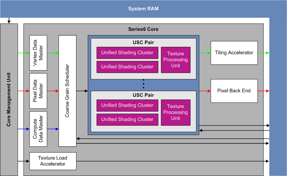
The image below shows a high level overview of the PowerVR Series 6 Graphics Processing Unit (GPU) core.
In this architecture the vertex and fragment stages share the same Unified Shading Cluster (USC) cores. These cores can either output their result to the Tiling Accelerator (TA) or the Pixel Back End (PBE). The USC cores are fed by 3 types of data masters and a scheduler. Each pair of USCs share a Texture Processing Unit (TPU).
The Texture Load Accelerator (TLA) handles converting texture data into optimal format and the acceleration of 2D surface operations such as blits.
USC
The image below shows the layout of a single USC. A USC uses the Common Store (USCCS) for fetching uniform data and the iterator for getting interpolated varying data. It is also fed by the fine grain scheduler that takes resident tasks to be executed.
The USC contains numerous ALU instances each working on a thread. These could be a vertex task, a pixel task, and so on. There are 16 instances in a group and the instances in a group execute the same instructions.
Each group of 1024 ALU instances share a Unified Store (US) that they can use to store data temporarily. Each ALU instance has space for about 24 floats in a shared US. Although it is possible to have more than 24 floats in the US for each ALU instance, it is not advised as in that case occupancy suffers.

USC ALU
The layout of a single ALU pipeline is shown below. Most of the USC instructions run on this pipeline, and it is best to utilise all the stages in a given path in this pipeline.
For example:
It is possible to execute:
two F16 sum of products (SOP) instructions
plus the F32 <-> F16 conversions
plus the
mov/output/packinstruction all in one cycle
On some of the PowerVR hardware there is the possibility of executing 4 SOPMAD instructions in one cycle.
It is also possible to execute:
an FP32 multiply-add (MAD) and an FP32/INT32 MAD/UNPACK instruction
plus a test (conditional) instruction
plus the
mov/output/packinstruction in one cycle
This allows for performing a conditional mov.
If there is bitwise work to be done, it is possible to issue:
a bitwise MASK or SHIFT/COUNT
a bitwise logical operation
a bitwise shift
a test
the
mov/output/packinstruction all in one cycle
It is also possible to execute a single complex operation (for example, rcp) and the mov/output/pack instruction in one cycle.
Lastly, an interpolate/sample instruction plus the usual mov/output/pack instruction can be executed in one cycle.

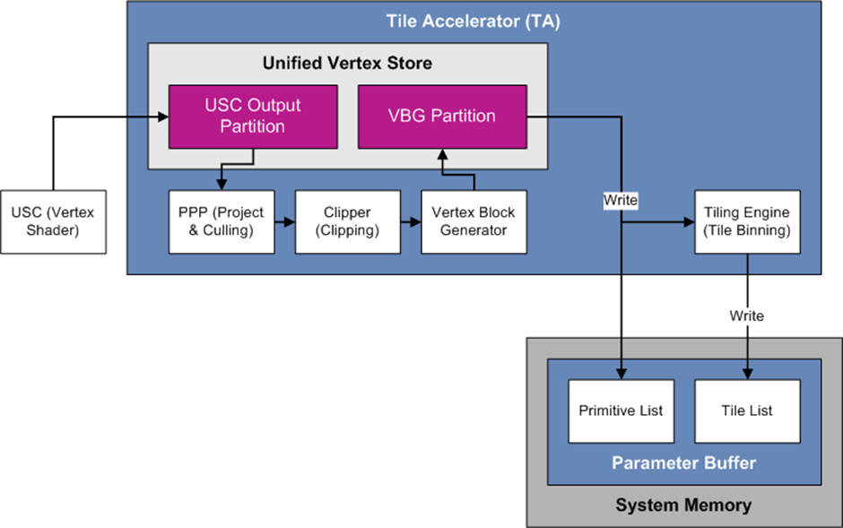
Vertex Processing Pipeline
The image below shows the various stages a vertex goes through after being processed by the vertex shader.
The end result of this process is a list of primitives that are projected and clipped. In addition, a list containing which primitive belongs to a given tile is also produced.
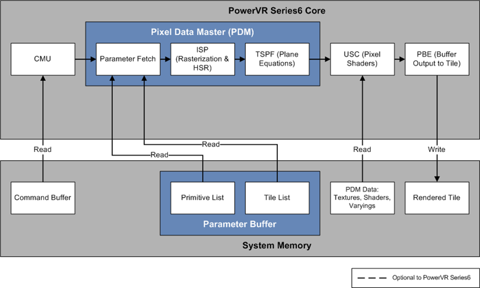
Pixel Processing Pipeline
After the tiling process is complete, tiles are processed at the pixel stage. Primitives are rasterized, hidden surfaces are removed and plane equations are calculated for interpolating vertex data.
Then, pixel shaders are executed and their result is written to the pixel buffer.