Configuring the Editor
Configuring the Editor
PVRStudio allows you to configure the text editor to suit your specific needs. To configure the editor, select Tools > Options > Text Editor.
These settings apply to all projects. To specify editor behavior for an open project, select Projects > Editor. For more information, see Specifying Editor Settings. You can also specify indentation settings separately for C++ and other files either globally or for the open project. For more information, see Indenting Text or Code.
You can perform the following configuration actions:
Set the font preferences and apply color schemes for syntax highlighting in Font & Colors.
Specify definition files for syntax highlighting for other types of files than C++ in Generic Highlighter.
Set tabs, indentation, the handling of whitespace, and mouse operations in Behavior.
Set various display properties, such as highlighting and folding blocks or text wrapping in Display.
Add, modify, and remove code snippets in Snippets.
View and remove text editing macros in Macros.
Configure code completion in Completion.
-
Run the main editor in a manner similar to the Vim editor in the FakeVim mode.
Specifying Text Editor Settings
Set the font preferences and apply color schemes for syntax highlighting in Tools > Options > Text Editor > Font & Colors.
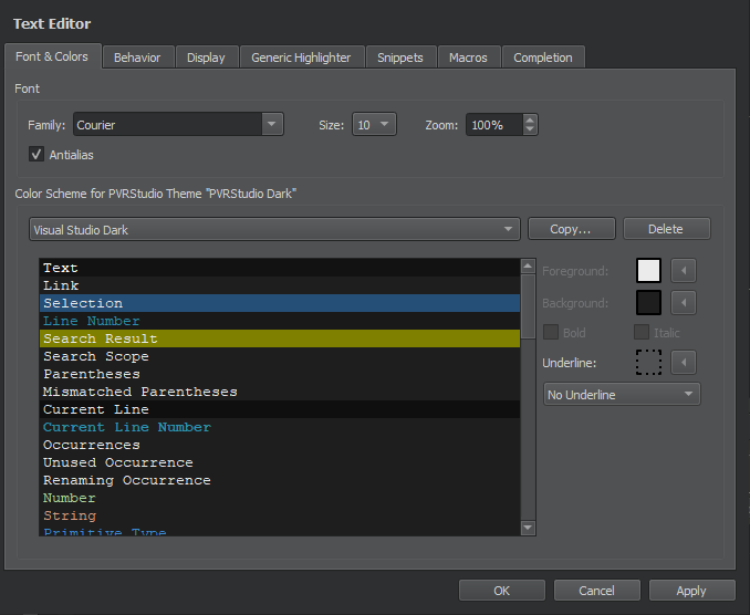
Configuring Fonts
You can select the font family and size. You can specify a zoom setting in percentage for viewing the text. You can also zoom in or out by pressing Ctrl++ or Ctrl+-, or by pressing Ctrl and rolling the mouse button up or down. To disable the mouse wheel function, select Tools > Options > Text Editor > Behavior and deselect the Enable scroll wheel zooming check box.
Antialiasing is used by default to make text look smoother and more readable on the screen. Deselect the Antialias check box to turn off antialiasing.
Defining Color Schemes
You can select one of the predefined color schemes for syntax highlighting or create customized color schemes. The color schemes apply to highlighting C++ files, GPU shaders and generic files.
To create a color scheme:
Select Tools > Options > Text Editor > Fonts & Color > Copy.
Enter a name for the color scheme and click OK.
In the Foreground field, specify the color of the selected code element.
In the Background field, select the background color for the code element.
The backgound of the Text element determines the background of the code editor.
When you copy code from PVRStudio, it is copied in both plain text and HTML format. The latter makes sure that syntax highlighting is preserved when pasting to a rich-text editor.
File Encoding
To define the default file encoding, select Tools > Options > Text Editor > Behavior, and then select a suitable option in Default encoding.
PVRStudio requires UTF-8 encoded source files. However, the Default encoding field still displays the value System if the default system encoding is set to UTF-8.
Detecting the correct encoding is tricky, so PVRStudio will not try to do so. Instead, it displays the following error message when you try to edit a file that is not UTF-8 encoded: Error: Could not decode “filename” with “UTF-8”-encoding. Editing not possible.
Using FakeVim Mode
In the FakeVim mode, you can run the main editor in a manner similar to the Vim editor. To run the editor in the FakeVim mode, select Edit > Advanced > Use Vim-style Editing or press Alt+V,Alt+V.
Supported Modes and Commands
In the FakeVim mode, most keystrokes in the main editor will be intercepted and interpreted in a way that resembles Vim. Most of the supported commands can be followed by a motion command or executed in visual mode, or they work with registers or can be prefixed with a number of repetitions.
The following sections describe the commands emulated in the supported modes and how they diverge from Vim in functionality:
Normal
Visual
Command line (:)
Insert and replace
For more information on using Vim, see Documentation on the Vim web site.
Normal and Visual Modes
Basic movement, such as
h/j/k/l,<C-U>,<C-D>,<C-F>,<C-B>,gg,G,0,^,$Word movement, such as
w,e,b- Inner/a movement, such asciw,3daw, ya{fandtmovement -[ and \c ]movement{ and } paragraph movement
Delete/change/yank/paste with register
Undo and redo
<C-A>and<C-X>increase or decrease a number in decimal, octal, or hexadecimal format (for example128<C-A>on or before"0x0ff"changes it to"0x17f") -.repeats the last change/search,?search,*,#,n,N- most of regular expression syntax is used in Vim except that\<and\>are the same as\bin QRegExp -@andq(macro recording and execution) special keys are saved as<S-Left>Marks
gvgoes to last visual selection; can differ if text is edited around itIndentation using
=,<<,>>, with movement, count, and in visual modeto upper/lower, such as
~,gU,gu-i,a,o,I,A, andOenter insert modeScroll window, such as
zt,zb,zz- Wrap line movement, such asgj,gk,g0,g^,g$
Command Line Mode
:map,:unmap,:inoremap, and so on -:sourceprovides very basic line-by-line sourcing of vimrc files:substitutesubstitutes an expression in a range -:'<,'>!cmdfilters through an external command (for example, sorts the lines in a file with:%!sort) -:<range>sor[t][!]:.!cmdinserts the standard output of an external command -:read:yank,:delete,:change-:move,:join:20goes to an address -:history:registers,:display-:nohlsearch:undo,:redo-:normal:<,:>
Insert Mode
<C-O>executes a single command and returns to insert mode -<C-V>inserts a raw character<insert>toggles replace mode
Options
Use :set ... to set the options listed in the following table:
Long Name |
Short Name |
Arguments |
|---|---|---|
|
|
|
|
|
|
|
|
|
|
|
|
|
|
|
|
|
|
|
|
|
|
|
|
|
|
A combination of the following
characters: |
|
|
|
|
|
|
|
|
|
|
|
|
|
|
|
|
|
|
|
|
|
|
|
|
|
|
|
|
|
|
|
|
|
|
|
Vimrc Example
" highlight matched
set hlsearch
" case insensitive search
set ignorecase
set smartcase
" search while typing
set incsearch
" wrap-around when searching
set wrapscan
" show pressed keys in lower right corner
set showcmd
" tab -> spaces
set expandtab
set tabstop=4
set shiftwidth=4
" keep a 5 line buffer for the cursor from top/bottom of window
set scrolloff=5
" X11 clipboard
set clipboard=unnamed
" use ~ with movement
set tildeop

" mappings
nnoremap ; :
inoremap jj <Esc>

" clear highlighted search term on space
noremap <silent> <Space> :nohls<CR>

" reselect visual block after indent
vnoremap < <gv
vnoremap > >gv

" MOVE LINE/BLOCK
nnoremap <C-S-J> :m+<CR>==
nnoremap <C-S-K> :m-2<CR>==
inoremap <C-S-J> <Esc>:m+<CR>==gi
inoremap <C-S-K> <Esc>:m-2<CR>==gi
vnoremap <C-S-J> :m'>+<CR>gv=gv
vnoremap <C-S-K> :m-2<CR>gv=gv
Mapping FakeVim Commands
To map commands entered on the FakeVim command line to actions of the PVRStudio core, select Tools > Options > FakeVim > Ex Command Mapping.
To map user commands to keyboard shortcuts, select Tools > Options > FakeVim > User Command Mapping. The user command mapped to the shortcut is executed by FakeVim as if you were typing it (as when replaying a macro).
Specifying FakeVim Options
To make changes to the Vim-style settings, select Tools > Options > FakeVim > General.
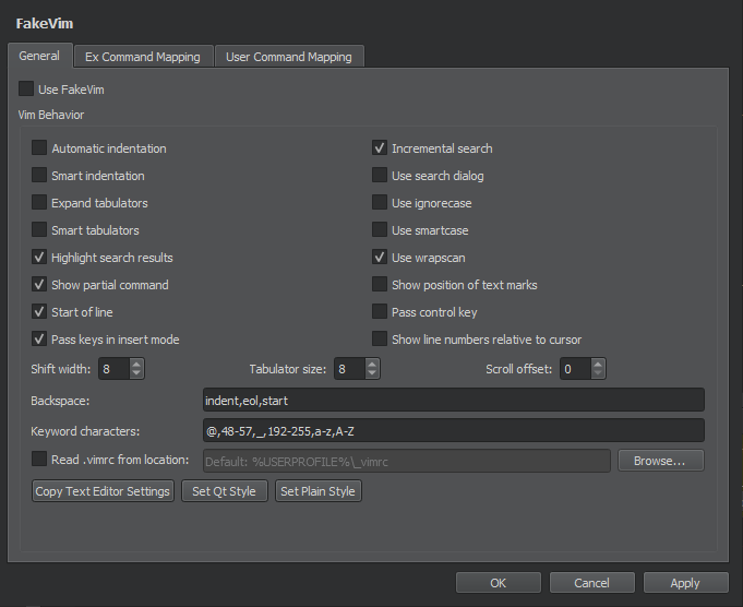
To preselect the indentation settings specified for the text editor, select Copy Text Editor Settings. To preselect a simple indentation style, select Set Plain Style. You can then change any of the preselected settings.
To use a Vim-style color scheme, select Tools > Options > Text Editor > Fonts & Color. In the Color Scheme list, select Vim (dark).
Quitting FakeVim Mode
To quit the FakeVim mode, unselect Tools > Options > FakeVim > Use FakeVim or press Alt+V,Alt+V.
You can temporarily escape FakeVim mode to access the normal PVRStudio keyboard shortcuts like Ctrl-R for Run by pressing , first.
Using Language Servers
For several programming languages, a language server is available that provides information about the code to IDEs as long as they support communication via the language server protocol (LSP). This enables the IDE to provide the following services:
Highlighting the symbol under cursor
Navigating in the code by using the locator or moving to the symbol definition
Inspecting code by viewing the document outline - Finding references to symbols
Code actions
Integrating diagnostics from the language server
By providing a client for the language server protocol, PVRStudio can support the above features for several other programming languages besides C++. However, the client does not support language servers that require special handling.
Adding MIME Types for Language Servers
PVRStudio uses the MIME type of the file to determine which language server to request information from when you open a file for editing. Add new MIME types or file patterns to match language servers. If you do not set at least one MIME type or file pattern, no files will be sent to the language server. This is done to avoid unnecessary traffic and inaccurate information, as files are only sent to the languge server if they are known to be handled by it. For more information about how PVRStudio uses MIME types, see Editing MIME Types.
Specifying Settings for Language Clients
To use a language server:
Select Tools > Options > Language Client (or PVRStudio > Preferences > Language Client > on macOS) to view a list of language servers.
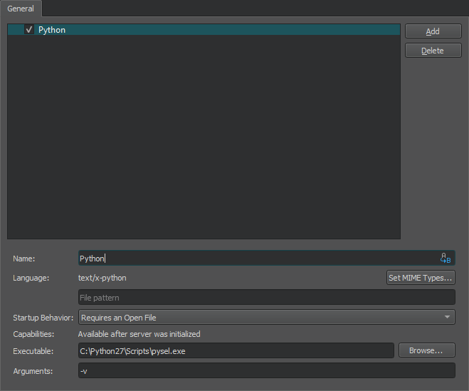
Select the check box next to the language server name to enable the language server.
Select Add to add language servers.
In the Name field, enter a name for the language server. Select the image:: images/replace.png (Variables) button to use a variable for the server name.
In the Language field, select Set MIME Types to select the MIME types of the files to send to the language server. In the field below, you can enter file patterns to extend the MIME types, separated by semicolons.
In the Startup behavior field, select whether the language server is started when PVRStudio starts or when a project or file with a matching MIME type is opened. The General Messages output pane displays information about the connection to the language server.
In the Capabilities field, you can see the features that are supported by the language server. Only some of them are implemented by PVRStudio.
In the Executable field, enter the path to the language server executable.
In the Arguments field, enter any required command line arguments. Select Variables to use variables as arguments.
To remove language servers from the list, select Delete.
Supported Locator Filters
The locator enables you to browse not only files, but any items defined by locator filters. The language client plugin supports the following locator filters:
Locating symbols in the current project (
:) - Locating symbols in the current document (.)Locating class (
c), enum, and function (m) definitions in your project
Reporting Issues
The language service client has been mostly tested with Python. If problems arise when you try it or some other language, please select Help > Technical Support to report them. The reports should include PVRStudio console output.
Editing MIME Types
PVRStudio uses the MIME type of the file to determine which mode and editor to use for opening the file. For example, PVRStudio opens C++ source and header files in the C++ editor, and images in the image viewer. For some MIME types, you can change the editor that is used to open the files of that type by default.
To identify the MIME type of a file, PVRStudio uses matching by pattern and matching by contents. First, PVRStudio looks at the filename to check whether it matches the patterns specified for any MIME type. If no match is found, it checks the contents of the file for magic headers specified for the file.
The magic headers can contain the following types of values: string, host, big-endian, little-endian, and byte. PVRStudio interprets the values according to the Shared MIME-info Database specification.
PVRStudio searches for the value within a specified range in the files and takes the priority of the magic header into account. If you specify wide search ranges, openging files in PVRStudio might take a long time. Therefore, you are advised to use the recommended values for the range and priority of the magic header.
If your files do not match the predefined MIME types, you can edit the MIME types to add filename extensions and magic headers. You cannot add new MIME types, however.
To edit MIME types:
Select Tools > Options > Environment > MIME Types.
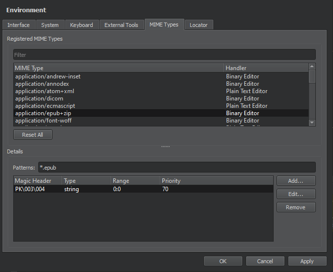
In MIME Type, select a MIME type.
In Patterns, add the filename extension for the type of files that you want to identify as having this MIME type.
Click Add to add Magic Headers.
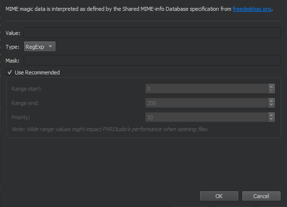
In the Value field, specify a text string or bytes that appear in the files.
In the Type field, select the type of the value.
In the Mask field, specify the number to combine the value in the file with using the AND operator before comparing it to the specified value. You can specify any numbers as masks for numerical types, whereas masks for strings must be in base 16, and start with 0x.
Note: You are recommended not to change the range and priority, because it might cause problems when opening files in PVRStudio.
In Handler, double-click the editor name to display a context-menu where you can select another editor to open the file in by default. The menu is available only if alternative suitable editors are available.
Click OK.
Even if an alternative editor is not listed for a MIME type, you can
still change the editor that is used to open the files of a
particular type. Remove the filename extension from the current MIME
type and add it to a MIME type that is handled by the editor you want
to use. For example, to edit Linux kernel device tree source (.dts)
files with the text editor, delete the pattern *.dts from the MIME type audio/vnd.dts (where it represents the digital surround
audio file format), and add it to the text/plain MIME type. You
can use the Filter field to find the MIME type that currently
contains a filename extension.
To revert the changes you have made to the MIME type definitions, select Reset MIME Types. To revert the changes you have made to the default editors, select Reset Handlers.
Note: If you now select OK or Apply, you permanently lose all your own patterns and magic headers. The changes are reverted the next time you start PVRStudio.
Modeling
You can use the model editor to create Universal Modeling Language (UML) style models with structured and behavioral diagrams that provide different views of your system. However, the editor uses a variant of UML and only a subset of properties are provided for specifying the appearance of model elements.
Structural diagrams represent the static aspect of the system and are therefore stable, whereas behavioral diagrams have both static and dynamic aspects.
You can create the following types of structural diagrams:
Package diagrams, which consist of packages and their relationships, and visualize how the system is packaged.
Class diagrams, which consists of classes, dependencies, inheritance, associations, aggregation, and composition, and provide an object-oriented view of a system.
Component diagrams, which represent a set of components and their relationships, and provide an implementation view of a system.
Deployment diagrams, which represent a set of software and hardware components and their relationships, and visualize the deployment of a system.
You can create the following types of behavioral diagrams:
Use case diagrams, which consists of actors, use cases, and their relationships, and represent a particular functionality of a system.
Activity diagrams, which visualize the flow from one activity to another.
Sequence diagrams, which consist of instances and specify where the instances are activated and destroyed and where their lifeline ends.
Using the Model Editor
You can create models that contain several different structural or behavioral diagrams. You can add elements to the diagrams and specify properties for them. You can either use standard model elements or add your own elements with custom icons.
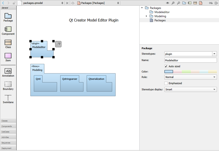
You can add model elements to diagrams in the following ways:
Drag and drop model elements from the element tool bar (1) to the editor (2).
Select tool bar buttons (3) to add elements to the element tree (4).
Drag elements from the element tree to the editor to add them and all their relations to the diagram.
Drag and drop source files from the sidebar views to the editor to add C++ classes or components to diagrams.
You can group elements by surrounding them with a boundary. When you move the boundary, all elements within it are moved together. Similary, drag a swimlane to the diagram. When you move the swimlane, all elements right to the swimlane (for vertical swimlanes) or below it (for horizontal swimlanes) will be moved together. A vertical swimlane is created when you drop the swimlane icon on the top border of the diagram and a horizontal swimlane is created when you drop the icon near the left border.
Classes or other objects that you lay on packages are moved with the packages. You can move individual elements and modify their properties (5) by selecting them. You can also use multiselection to group elements temporarily.
To align elements in the editor, select several elements and right-click to open a context menu. Select actions in the Align Objects menu to align elements horizontally or vertically or to adjust their width and height.
Drag the mouse over elements to select them and apply actions such as changing their stereotype or color. A stereotype is a classifier for elements, such as entity, control, interface, or boundary. An entity is usually a class that is used to store data. For some stereotypes, a custom icon is defined. You can assign several comma-separated stereotypes to one element.
To add related elements to a diagram, select an element in the editor, and then select Add Related Elements in the context menu.
By default, when you select an element in a diagram, it is highlighted also in the Structure view. To change this behavior so that selecting an element in the Structure makes it highlighted also in the diagram, click and hold the image:: images/linkicon.png button, and then select Synchronize Diagram with Structure. To keep the selections in the diagram and the Structure view synchronized, select Keep Synchronized.
To zoom into diagrams, select the Zoom In toolbar button, press Ctrl++, or press Ctrl and roll the mouse wheel up. To zoom out of diagrams, select Zoom Out, press Ctrl+-, or press Ctrl and roll the mouse wheel down. To reset the diagram size to 100%, select Reset Zoom or press Ctrl+0.
To print diagrams, press Ctrl+C when no elements are selected in the editor to copy all elements to the clipboard by using 300 dpi. Then paste the diagram to an application that can print images.
If you copy a selection of elements in the editor, only those elements and their relations will be copied to the clipboard as an image.
To save diagrams as images, select File > Export Diagram. To save only the selected parts of a diagram, select Export Selected Elements.
Creating Models
You can use wizards to create models and scratch models. A scratch model can be used to quickly put a temporary diagram together. The wizard creates the model file in a temporary folder without any input from you. Therefore, you can assign a keyboard shortcut to the wizard and use it to create and open models with empty diagrams.
To create models:
Select File > New File or Project > Modeling > Model > or Scratch Model > Choose to create a model or a scratch model.
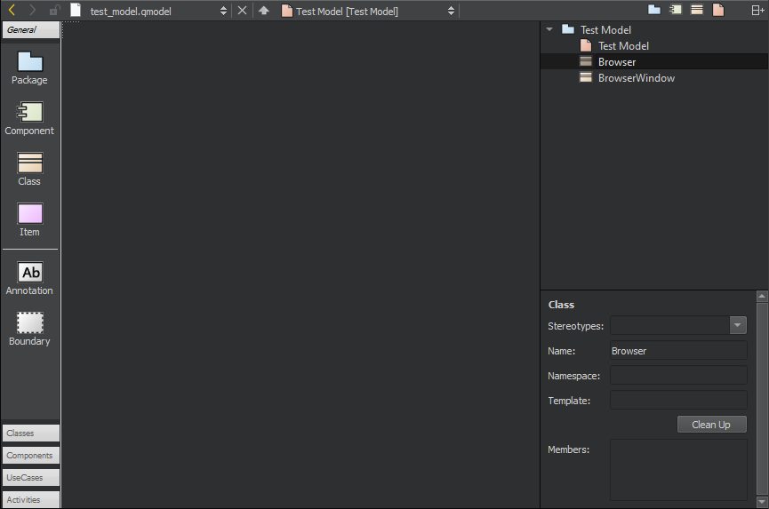
Drag and drop model elements to the editor and select them to specify properties for them:
In the Stereotypes field, enter the stereotype to apply to the model element or select a predefined stereotype from the list.
In the Name field, give a name to the model element.
Select the Auto sized check box to reset the element to its default size after you have changed the element size by dragging its borders.
In the Color field, select the color of the model element.
In the Role field, select a role to make the model element color lighter, darker, or softer. You can also remove color and draw the element outline or flatten the element by removing gradients.
Select the Emphasized check box to draw the model element with a thicker line.
In the Stereotype display field, select:
Smart to display the stereotype as a Label, a Decoration, or an Icon, depending on the properties of the element. For example, if a class has the stereotype interface, it is displayed as an icon until it becomes displayed members, after which it is displayed as a decoration.
None to suppress the displaying of the stereotype.
Label to display the stereotype as a line of text using the standard form above the element name even if the stereotype defines a custom icon.
Decoration to show the standard form of the element with the stereotype as a small icon placed top right if the stereotype defines a custom icon.
Icon to display the element using the custom icon.
To create a relation between two elements, select the arrow icon next to an element and drag it to the end point of the relation.
Select the relation to specify settings for it, according to its type: inheritance, association, or dependency. You can specify the following settings for dependency relations, which are available for all element types:
In the Stereotypes field, select the stereotype to apply to the relation.
In the Name field, give a name to the relation.
In the Direction field, you can change the direction of the connection or make it bidirectional.
To move the end of a relation to a different element, grab the end point and drop it over another element that accepts relations of that type. For example, only classes accept inheritances and associations.
To create sampling points that divide a relation into two connected lines, select a relation and press Shift and click on the relation line.
If possible, the end point of a relation is moved automatically to draw the line to the next sampling point either vertically or horizontally.
To remove a sampling point, press Ctrl and click the sampling point.
To group elements, drag and drop a Boundary element to the editor and resize it to enclose the elements in the group.
Creating Package Diagrams
You can add nested package elements to a package diagram. The depth of the elements in the diagram corresponds to the depth of the structured model. Elements stacked on other elements of the same type are automatically drawn in a darker shade of the selected color.
Right-click a package to open a context menu, where you can select Create Diagram to create a new package diagram within the model. You can drag and drop items from the element tree to the diagram.
To update the include dependencies of the package, select Update Include Dependencies.
Creating Class Diagrams
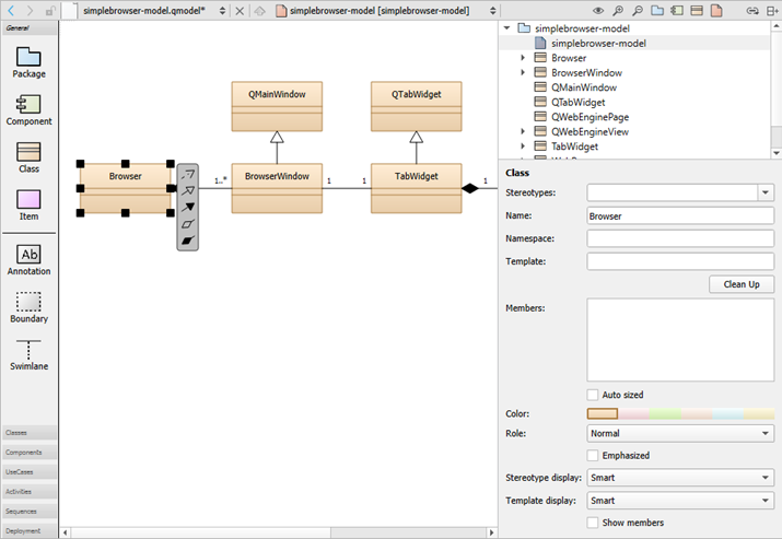
To create class diagrams:
To add C++ classes to class diagrams, drag and drop files from Projects to the editor, and select Add Class.
In addition to the common element properties, you can specify the following properties:
In the Template field, specify the template to use.
In the Template display field, select the display format for the template:
Smart displays the template as Box or Angle brackets, depending on the class properties.
Box displays the template in a small box with a dotted border in the top right corner of the class icon.
Angle brackets writes the template in angle brackets behind the class name using the C++ syntax.
In the Members field, specify members for the class, as described in Specifying Members.
Select Clean Up to format the contents of the Members field depending on their visibility (private, protected, public) and following the rules set for whitespace, line breaks, and so on.
Select the Show members check box to show the members in the diagram.
To navigate from a class in a diagram to the source code, double-click the class in the editor or select Show Definition in the context menu.
Adding Relations
Elements in class diagrams can have the following types of relations: inheritance, association, and dependency. The end points of association relations can have the following properties: role, cardinality, navigable, and relationship.
To create self-relations, start creating a new association and press Shift to create a new sampling point while dragging the association. Create another sampling point and drop the association at the same class.
To add more points, press Shift and click a relation. To delete a point, press Ctrl and click a point.
Specifying Members
To specify members for the class, enter each member on a separate
line using a C++ like syntax. For example, the following lines define
the method m that is private, virtual, and constant:
private:
virtual int m(string a) const;
You may group members:
[Geometry]
QPointF position;
QSizeF size;
You may add stereotypes to members:
<<setter>> setPosition(const QPointF &pos);
There are some limitations of the parser:
Multi-line declarations work only if lines are wrapped within nested brackets:
void setSize(int width,
             int height);
Preprocessor macros will not be translated.
Function pointer declarations are interpreted as methods.
throw()andnoexpect()specifiers are not ignored but will make the declaration a method.
Creating Component Diagrams
You can add source code components, such as libraries, databases, programs, and architectural layers to a component diagram. To add components to component diagrams, drag and drop source code from Projects to the editor, and select Add Component.
To navigate from a component in a diagram to the source code, double-click the component in the editor or select Show Definition in the context menu.
Adding Custom Elements
The model editor provides the following built-in element types: package, component, class, and item. For package, component, and class elements, you can specify custom icons. The color, size, and form of the icon are determined by a stereotype. If you attach the stereotype to an element, the element icon is replaced by the custom icon. For example, you can attach the entity and interface stereotypes to classes and the database stereotype to components.
The use case and activity diagrams are examples of using the built-in item element type to add custom elements. The item element has the form of a simple rectangle. The use case illustrates how to use a custom icon for an item. The attached stereotype is called usecase but it is hidden. Therefore, if you drag the use case to the diagram, it is shown as a use case but no stereotype appears to be defined and you can attach an additional stereotype to the use case.
Color and icons are attached to elements in use case and activity
diagrams by using a simple definition file format. For example, the
following code adds the UseCase custom element:
Icon {
    id: UseCase
    title: "Use-Case"
    elements: item
    stereotype: 'usecase'
    display: icon
    width: 40
    height: 20
    baseColor: #5fb4f0
    Shape {
        Ellipse { x: 20, y: 10, radiusX: 20, radiusY: 10 }
    }
}
For more information about the available options, see standard.def in the share/qtcreator/modeleditor directory in the PVRStudio installation directory. It describes also how to define custom relation types and templates for existing types (such as a composition relation that can be drawn between classes).
You can add your own definition file and save it with the file extension .def to add custom colors and icons for stereotypes, elements, or tool bars. Either store this file in the the same directory as the standard.def file or select the root element of a model and apply your .def file to the property Config path.